Description
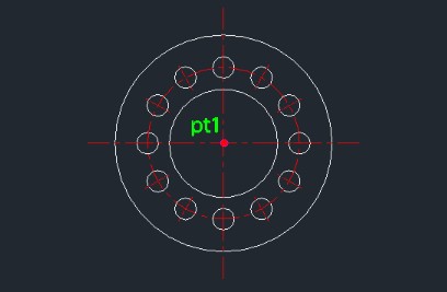
This tool automatically draws the side view of a flange, including the bolt hole centerlines.
- Efficient Drafting
- Instead of manually drawing multiple concentric circles and calculating bolt hole positions, this command generates the entire side profile based on a few parameters.
- Input
- Requires the center point, outer diameter, inner diameter, pitch circle diameter (PCD) for bolt holes, bolt hole diameter, and the number of bolt holes.
- Auto-Layer
- Automatically creates the center layer if it doesn't exist.
How to use
The complete side view of the flange, including bolt holes and centerlines, is drawn
- 1.Type fside in the command line and press Enter.
- 2.Click the Center Point for the flange.
- 3.Enter the Outer Diameter.
- 4.Enter the Inner Diameter.
- 5.Enter the PCD (Pitch Circle Diameter) for the bolt holes (the diameter of the circle passing through the bolt hole centers).
- 6.Enter the Bolt Hole Diameter.
- 7.Enter the Number of Bolt Holes.
Note
- For the front view of a flange, the post suggests using the existing COVER command.
Example
Included free
All 401 LISP utilities come free with every Cadopilar license.
Purchase any Cadopilar license and our team will install the complete suite for you. No additional charge, no setup headaches.
Contact us to get started →